Let’s take a look at my progress on my Creature Controller. This is the board that goes inside the Creatures themselves to control movement. I keep refining it as I go. This page is sort of my own museum where I can explain the decisions I made, and why.
Summer 2025 Version
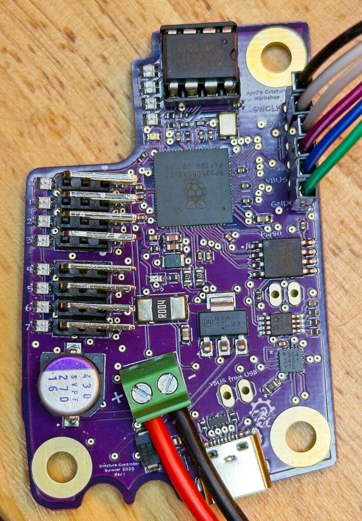
I designed the Summer 2025 version of the Creature Controller to fix a bunch of the flaws from the August 2024 version, as well as some nice upgrades . These include:
- Removal of all power supply components (replaced with a laptop power brick externally)
- Proactive monitoring of power use and temperature. If thresholds for either are surpassed for more than a configurable number of seconds, the controller cuts power to the motors.
- Full control of the power to each motor in software. Power is not turned on to the motor until a valid configuration and a first frame has been received from the controller.
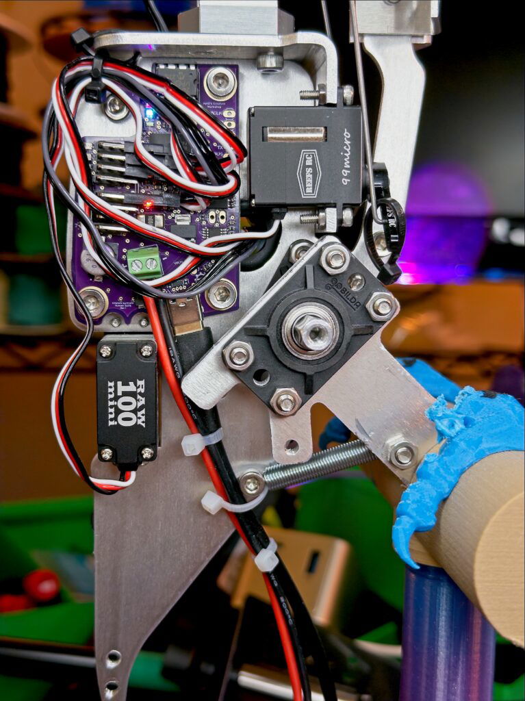
- It’s much smaller. It fits cleanly on the bird’s metal frame.
- Full ESD protection on the USB port, and polarity protection on the power inputs.
- Addition of a DIP8 socket for an I2C EEPROM. (More on that below.)
- Upgraded to the new RP2350B microcontroller. The expanded GPIO ports allowed me to move the external ADC and save board space. (This functionality is currently not present on the board, I didn’t have room for an extra row of pins.)
Power
The August 2024 edition of the Creature Controller had a fatal flaw that made it unusable. By putting all of the power regulation on the board itself I enabled the Creature Controller to get too hot. This lead to a miserable performance at Mephit Fur Meet 2024. I had implemented this with a vision of being able to set the voltage for each motor in software, enabling me to mix motors with different power needs together. I never ended up actually using this. The Summer 2025 edition moves all power regulation off the board and to nothing more than a simple laptop power supply. That allows me to keep the thing that generates heat off the set, and tucked safely under the table.
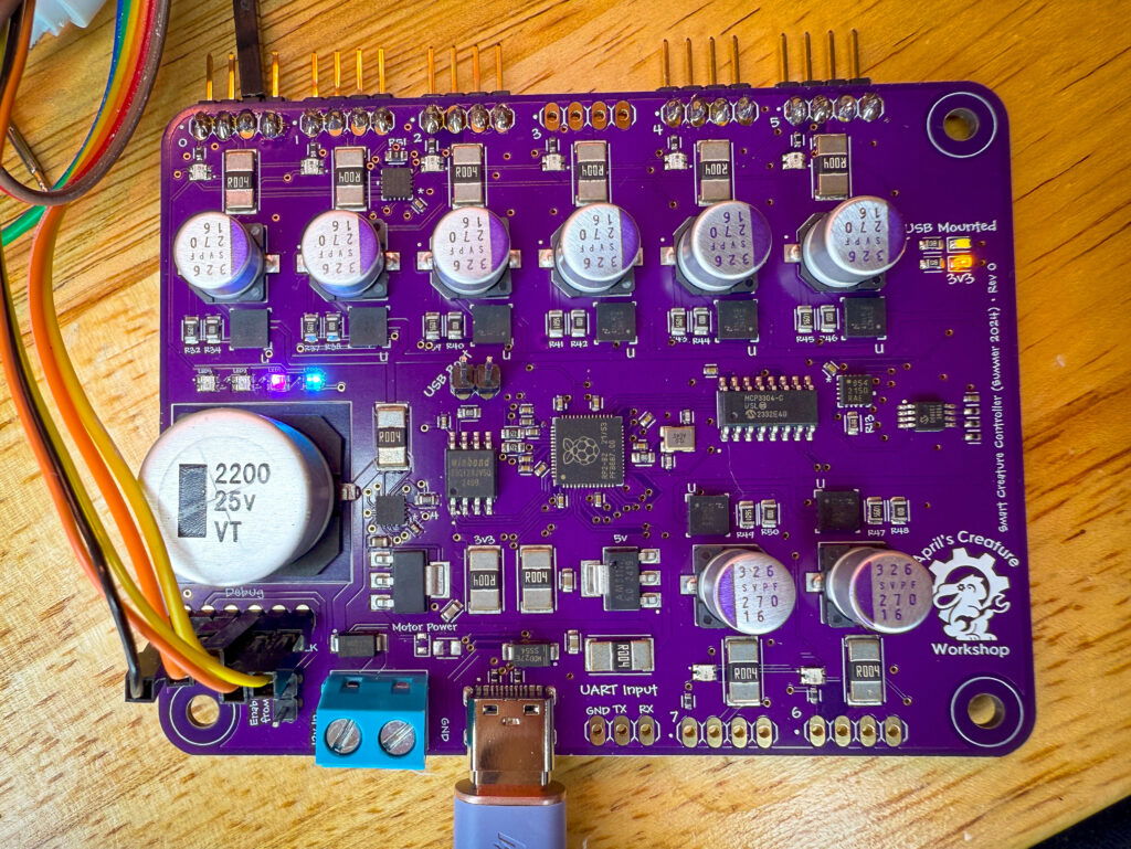
There is lots of power monitoring and switching present on the board, however!
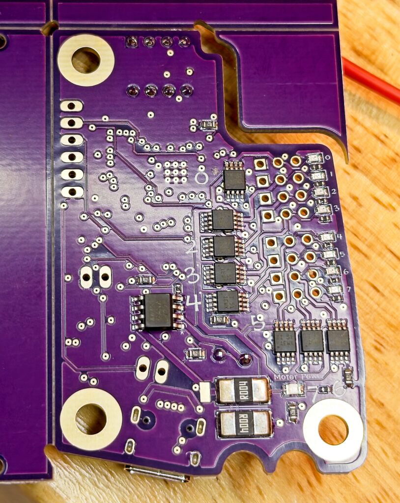
I populated the back of the board with eight commercial power control chips. Each of these chips controls a different motor, and enables me to turn power to the motor on and off via software. The LED next to each row of pins glows when power is turned on to the motor, enabling visual debugging.
The 2025 edition of the Creature Controller is the first one I’ve considered “production”! I’m using it full time on the creatures that live in my house. Since it monitors itself very well I am comfortable with walking away while a creature is powered up and moving, unlike all other versions!
Personality Module
The DIP8 socket at the top contains an I2C EEPROM that makes up the creature’s “personality module.” This module contains the creature’s name, serial number, logging level, software version, and USB PID/VID. I use this information when constructing the device name that’s returned to the host over USB, enabling me to make it easy to see which creature is on which device node on the Linux host. (This works via the /dev/serial/by-id tree in Linux.)
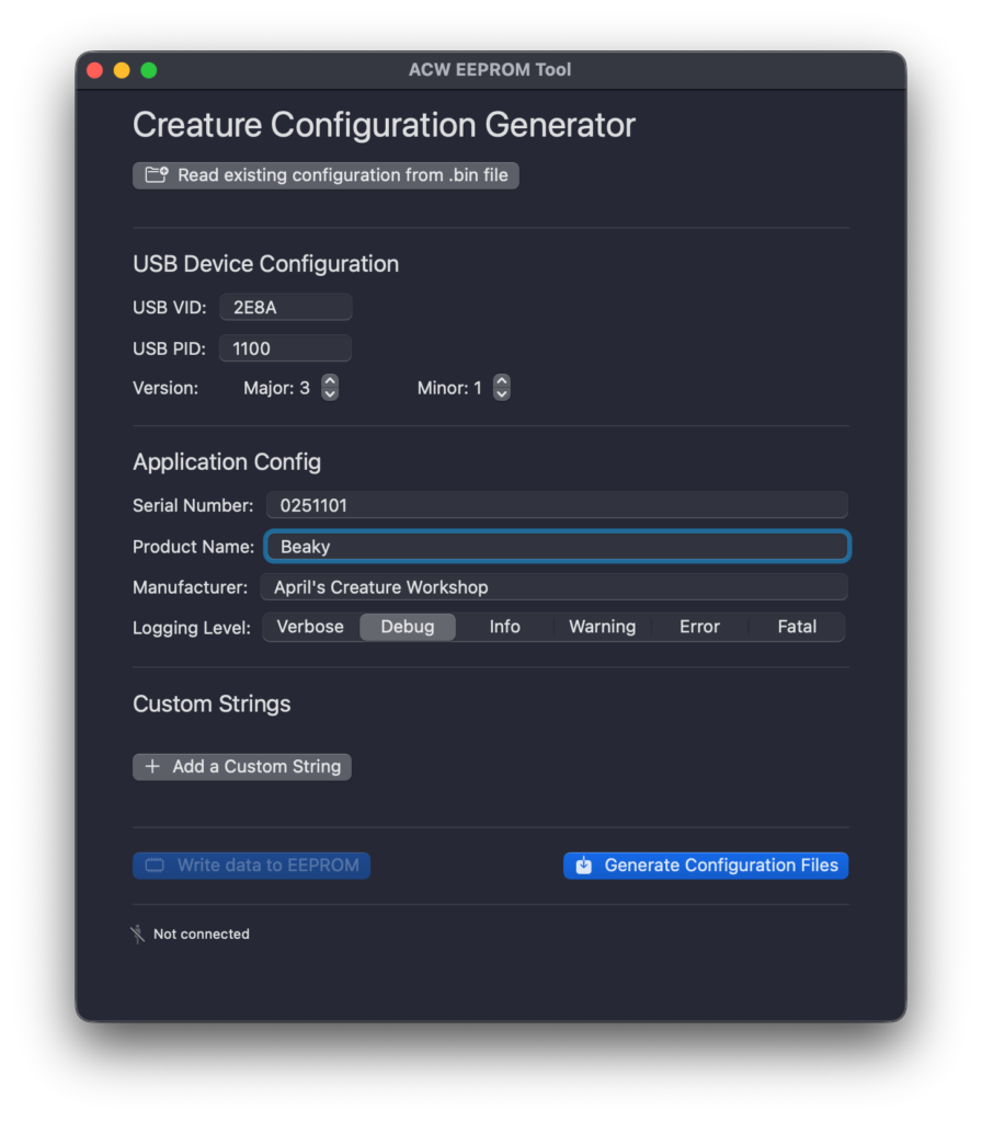
The personality module is configured via my “Creature Configurator.” It’s a simple SwiftUI app that writes out a binary file with the contents of the EEPROM, or can optionally connect to my I2C EEPROM programmer.
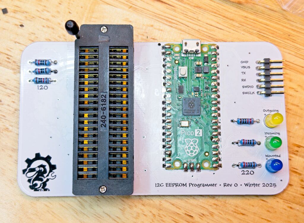
The I2C EEPROM programmer is a really simple device. When I hook it up to my Mac it presents itself as a serial port, and I wrote a little “shell” that runs on the programmer itself. It can be instructed to do things with nothing more than serial terminal. There’s no software needed on the Mac otherwise. (Since it’s only a CDC serial device, it will work on just about any modern computer.)
If there’s no personality module installed on the controller it will boot up in a default mode where it calls itself “Unknown Creature.”
August 2024 Version
The summer 2024 version of my Creature Controller has been a huge leap forward! This board combines all four of the previous boards into one, and switches the interface to USB.
New features:
- Onboard RP2040 chip, rather than having a dev board soldered on
- Three onboard PAC1954 ICs, to monitor the following things:
- Input (Both pre and post power protection)
- 5v regulator
- 3v3 regulator
- Each servo itself
- The voltage regulators are now SMD, and configurable via a voltage divider network
- Onboard temperature monitoring
- Eight channel ADC, allowing for use of servos that report their position
- Control protocol is now spoken over USB (allowing for easy debugging on a macOS machine)
Let’s look at each of these.
Onboard RP2040
I chose to integrate in my own RP2040 microcontroller, rather than solder on a devkit. This allows me to get a lot more bang for my buck on the board size, since I don’t have to deal with pads being 2.54mm apart from each other. This also allows it to speak USB to the controller, rather than use the traditional DMX controller.
I made decision to break up the functionality of the controller into two pieces. The controller software on a Pi (well, any device that has a USB port and a C++ compiler) that does all of other heavy lifting for state, and the onboard microcontroller that handles the actual positioning of the servos, as well as reporting the sensor data back to the Pi. The RP2040 doesn’t calculate movements, it only does what it’s told from the computer.
It took me a bunch of iterations to come up with this design! At first I realized that I was going to need sensors on the servo board if I wanted to support positional sensors, and that got me thinking about “what if I put an RP2040 on the servo board…” and eventually it all clicked that I could combine everything together.
Power Monitoring
My goal is to be able to run Creatures inside my house as if they are alive and living with me, so I wanted to make sure I was able to monitor their power. I chose the PAC1954 microcontroller because it’s fast, provides voltage, current, and power, and runs over I2C.
Why do this?
Because I kept getting burned on the old servo boards. 😅 There was a period there of about a year where I always had at least one voltage regulator shaped burn on my fingers, and I wanted to be able to detect shorts in software and kill power the moment a short was detected.
SMD Voltage Regulators
I made the decision to go with more modern voltage regulators for a few reasons. One, I can configure them as needed via a voltage divider network (those are 0805 resistors just for this reason), and they’re a lot smaller. The type I was using before sticks up a good 15-20mm, which eats up a lot of space. This new design is way cleaner and way smaller.
Temperature Monitoring
This turns out to be the most important sensor on the board!
I’m currently making things on my army of 3D printers. PLA and PETG are great materials, but they get soft at fairly low temperatures. I’ve had failures because PLA parts got too soft and failed, so I wanted to be able to combat this.
Eight Channel ADC
I’ve included an eight channel Analog to Digital converter. It’s the same chip that’s in my Creature Joystick, so I know it well. My goal is to unlock the use of servos that have positional feedback, but I haven’t actually done it yet. (But have confirmed that it all works.)
My goal here is to be able to provide a controlled startup to a Creature. The servos I use are powerful, and I’ve had accidents where, when a Creature is first powered up, the forces on the plastic snaps a part as it jerks into position. I’m hoping to be able to use positional feedback to know where the motors are when it’s first powered on, and then use this information to slowly move the Creature into a home position.
Watching it all go!
Here’s a short video showing Mango up and running with this version of the Creature Controller!
June 2023 Version
This was the first version of my Creature Controller. It was broken up over four different board.
What was my vision in breaking it up over four boards? I wanted to make re-usable modules that I could re-use over and over again. They were designed in such a way that I could make them by hand as I needed to.
Servo Module
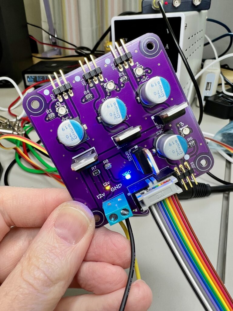
This is the servo module. It was designed to be the board that was tucked up into the creature itself. It has up to four channels (I also made a smaller, two channel version), each with its own smoothing capacitor and voltage regulator. There’s no actual logic on board, it’s only an extension of the main logic board.
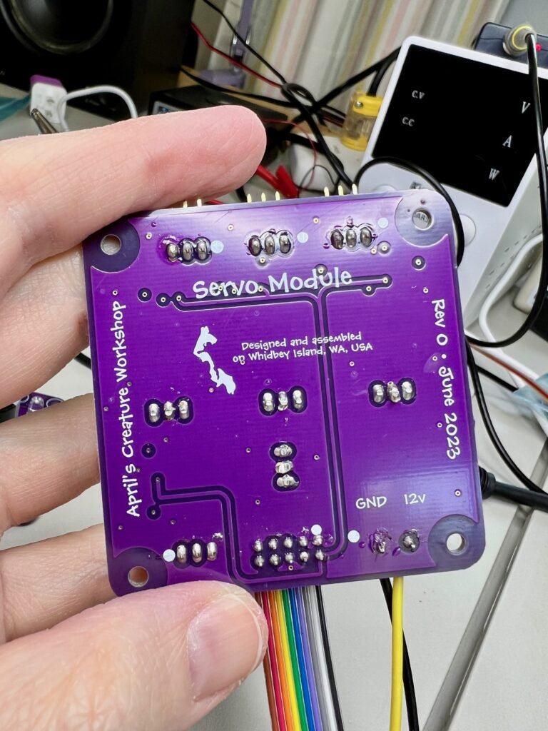
I designed the system such that I can put three of these off one logic controller. The ribbon cable links back to the logic board.
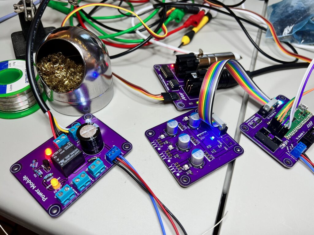
Power Module
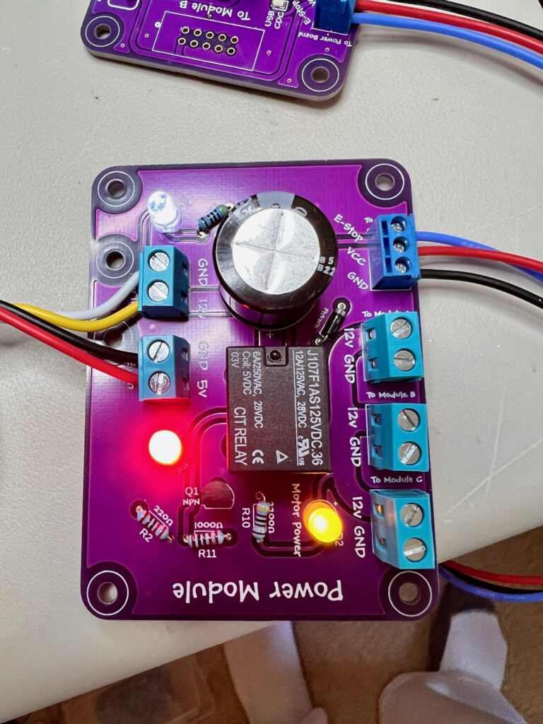
The power module has one main function. It allows for the controller to kill power to the motors in a hurry if needed. It comes up in a state where no power is being supplied on the 12v rail, and it waits for a signal from the logic board to act. (The E-Stop pin needs to be driven low.)
It uses an old school relay, mostly because I like hearing it go CLICK when the power comes on. 😍
Server HAT
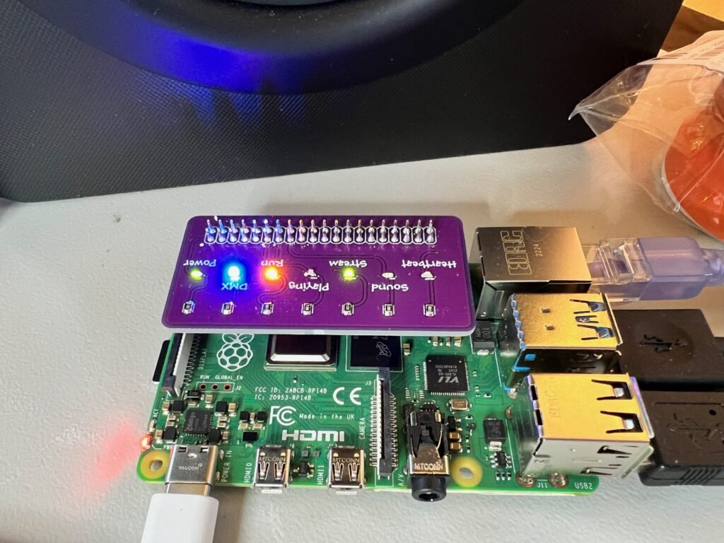
This was just a fun thing I made on a whim. It’s a little HAT for the server that shows what’s going on. (Power, DMX signal being sent, running, playing an animation, streaming packets being received, sound playing, and heartbeat.) It had no real purpose other than I thought it looked cool.
I don’t use this anymore. Now I do the “Virtual Status Lights” in software and it’s communicated over a web socket back to the Creature Console.